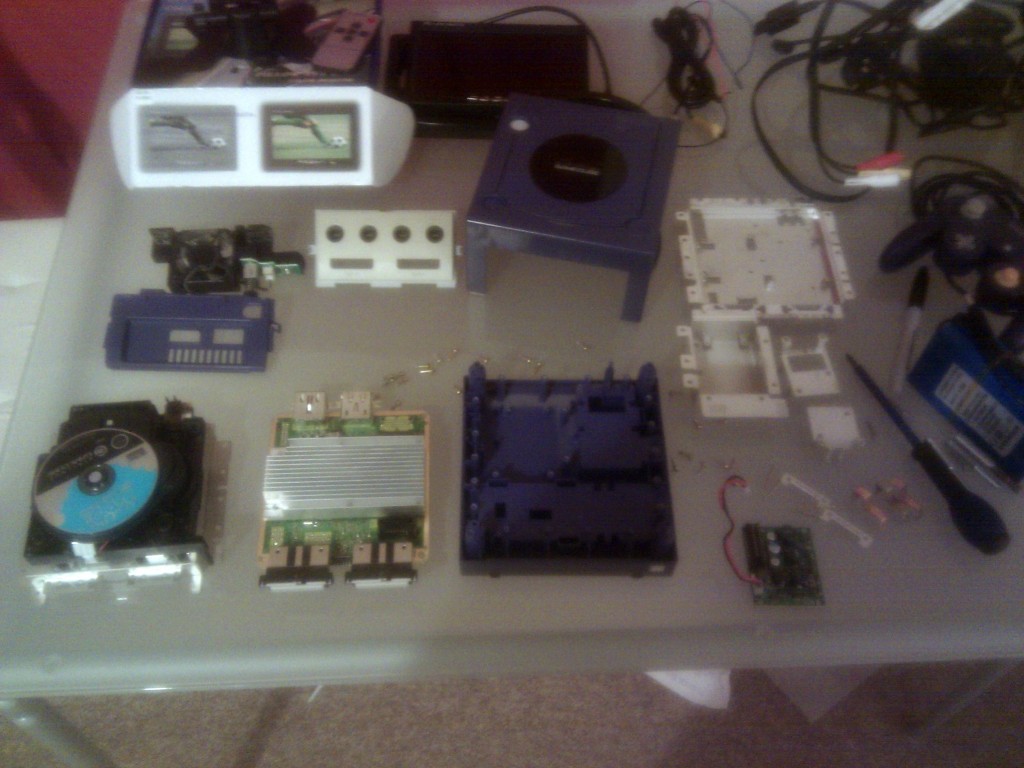
Ok so yesterday I began this Portable GameCube project by taking apart the donor console. Here’s a picture of all the parts I have so far for this project, should be everything I need apart from a few consumables and paint.
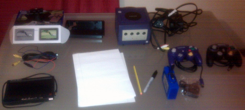
Picture quality sucks, but it was on my phone, anyway. On the left is the 7″ TFT screen and all the extra junk that came with it. It’s designed for use in a car or something but its actually a pretty good screen for only 20 quid, comes with a panel mounting plate, has two video inputs tehcnically one is for a rear view camera in a car with a remote switch to change between them. In the top right is the donor GameCube, cables and controllers. The issue with the controllers is that the switches are attached to a single PCB inside, so to cut the controller in half you have to cut the PCB which of course means it wont work any longer, so the second controller will be used with wires to connect up all the buttons and such.
Bottom right is the battery, its a 12V 9600mAh battery with a mains charger for japan or wherever it came from,I will probably get a few more of these as when I was figuring the size out a while back I think there was a load of extra room and more battery == more playtime, and longer battery life too since the current drain will be lower on each battery. Not pictured, there is a LED display and driver chip for a battery monitoring circuit so you can see how much battery is left, this’ll have to be set-up in situe so I’ll also have to get some variable resistors and other items to finish off that part.
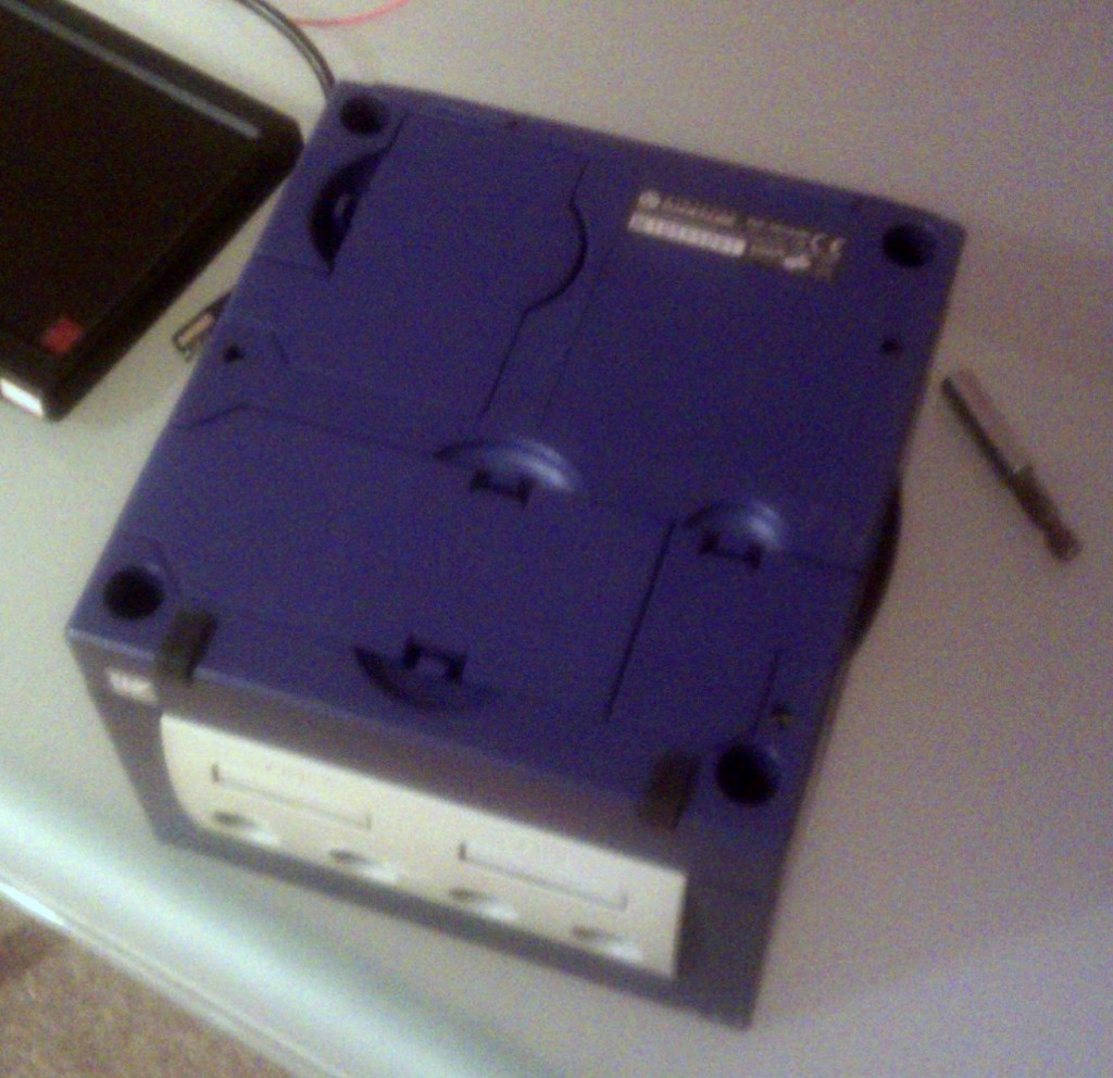
OK, so on with the dissassembly, there are 4 deep holes at the corners each of which has a screw at the bottom, but not a normal screw, oh no. Nintendo at least use a special headed screw which is kindof an inverse torx h ead. Instead of being a 6 sided cog shape imprint its a similar shape extruded instead, of course you need a special tool to undo these screws called a “Game Bit”. The right part is acutally pretty cheap, you can get both sizes for about 5 quid plus postage from ebay but the GameCube uses the larger of the two.
Right so you’ve bought your relatively special tools and you’ve undone the 4 screws that secure the top to the base. Flip the Gamecube over and lift the top of the case off, it should come away easily. Now you’re left with the actual Gamecube hardware and to be honest, its pretty small. Theres a laser lens in the top which you do not want to damage so best way to avoid it is to just put a disc in which will keep it covered and relatively safe.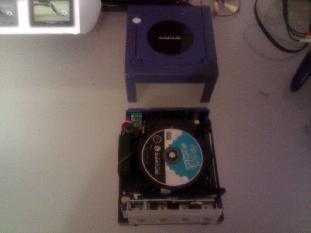
Now on the left is a fan assembly and at the front is the controller/memory card facia. All the mechanical parts for the disc cover are self contained in the case which is great as it means I don’t have to rebuild it all in a dodgey way, but the reset and power buttons are seperate and will have to be attached later on. The front facia is pretty easy to remove, it looks and feels pretty sturdy but actually you can just lift/pull ir forward and it unclips, just don’t pull it straight off.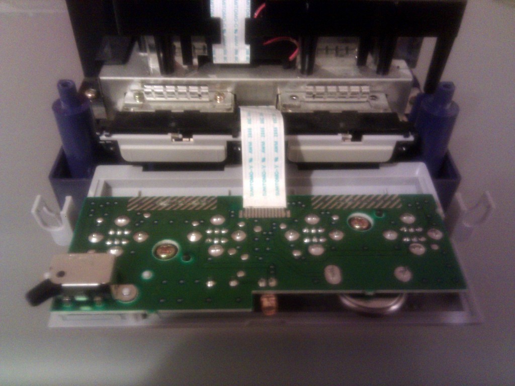
The ribbon cable at the back is actually quite strong but still, try and be a bit careful with it, as you can see it is soldered to the front panel not in a connector and that would be a bastard to fix. The back of the cable is just in a vertical slot on the main PCB and can be pulled straight up and out disconnecting the front panel entirely with the controller ports, which is good, but also with the reset switch and power on LED which is somewhat annoying. The memory card slots are connected directly to the main PCB which is an issue, but not unsolvable.
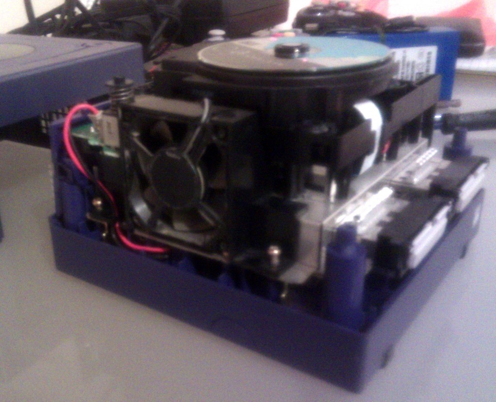
Next comes the fan assembly, there are two screws which hold it in place and are undone in the picture, and there is a power cable that runs through the fan to the small power PCB at the rear of the unit. Disconnect the red and black power lead and pull it out of the securing slot in the fan, the cable runs right down to the base so its best to just pull it to the side so it is out of the way. You have to full remove the two screws before removing the fan as it has to be pulled out laterally away from the unit due to the plastic piece going under the disc reader.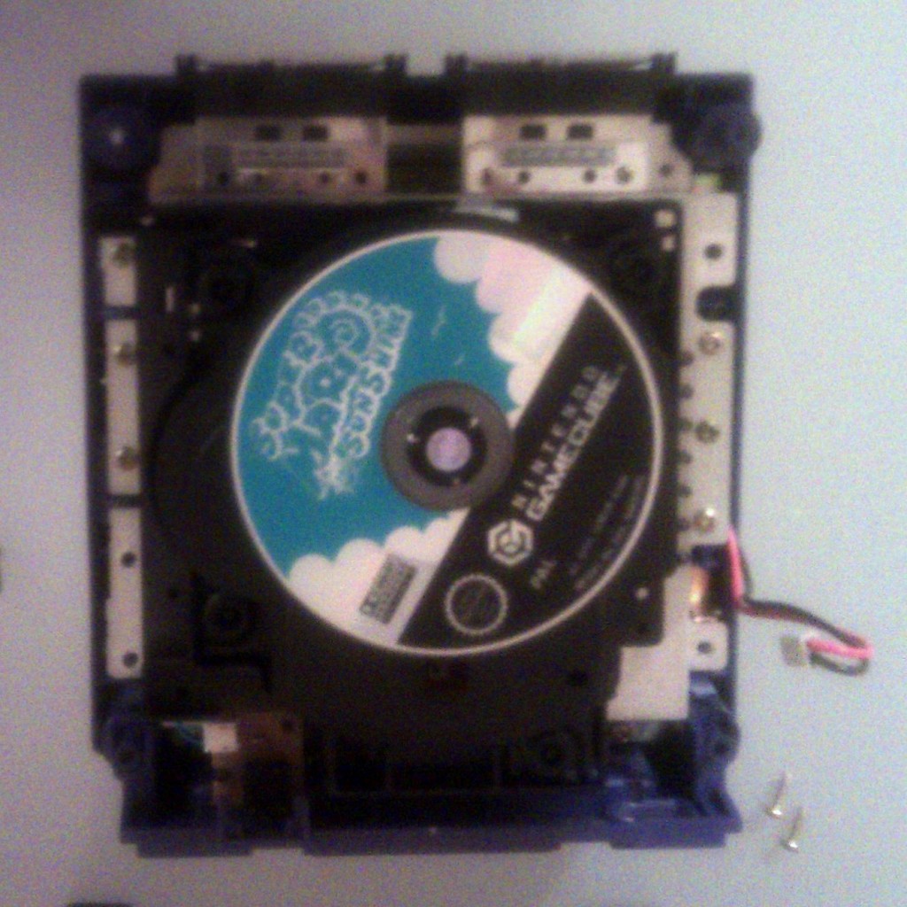
So with the fan you’ve removed 2 of the 20 screws securing the disc assembly to the main PCB.  There are 8 more that you can see on the sides on this picture and 4 more in the back that you can’t. There is also an additional 4 screws that hold the memory card slots together that have to be removed as well. The back plate is then attached in much the same way as the front panel and just pulls away, no cables attached to it. This then reveals the 4 remaining screws which allows you to remove the disc unit with relative ease as it just lifs off.
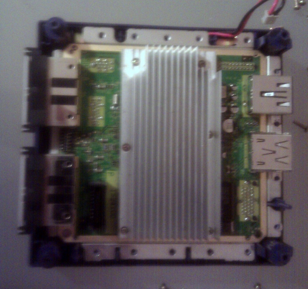
So here it is, the main core of the GameCube, with one pretty big heatsink. Now this is where it gets a bit tricky to see what to do next. There are no obvious screws holding the board in place but it wont budge. 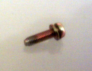 So there are those 6 heatsink screws… normally you don’t want to remove a heatsink if you can help it because you have to get thermal goo and reseat it and a world of other pains, but actually those 6 screws aren’t holding the heatsink, they hold the PCB to the base. Undo these with care as they have a small spring washer on them as well which you want to make sure you don’t lose assuming you want to attach the PCB to the metal base below it again, which I might. These spring washers just help to stop the screw losening under vibration by holding it tight against the threads once it has been done up and if you’ve ever picked up a GameCube whilst it is on it vibrates A LOT with the disc spinning. Anyway, after removing the screws the PCB just lifts out leaving the base and that power cable from earlier.
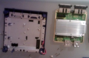
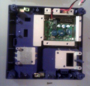 The large metal plate is held in by 4 screws and then just lifts out leaving only the power regulator circuit and some metal pieces for grounding and structural purposes. The power regulator is held in by 4 small screws and then just lifts out. This circuit will is important as it allows the GameCube to use the 12V power supply from the mains brick, or in my case, battery packs to give all the power rails the board needs, I’ve not checked it but at a guess there’s 12V, 3.3V and 1.8V supply rails, but there could well be other voltages too.
So that’s it, just lift out the regulator circuit and other bits of metal and you’ve disassembled the GameCube, pretty much entirely. There are other things you can disassemble if you want, like the disc drive assembly, but I want mine to continue to work after I’ve finished.
There are two things I’d like to say about this process. Firstly, I’d normally try and keep track of where screws came from and there’s loads of methods, you can label everything and write it all down, put the screws back where they came from, lay them out in a map format so you can immediately see where they came from, but I didn’t, there is only 4 types of screw in the gamecube and it’s pretty obvious where they go, as its mostly the large brass ones that hold the disc drive in place.
Secondly, the GameCube is a really well built piece of kit, there were no connectors to undo for the most part and no tricky parts to undo… execept the gameb bit obviously. This is something usually really overlooked by electronics designers, usually you’re lucky if the PCB fits the case properly once it has parts on it, and working in the test an repair department for a company that makes a load electronics, it can be a real pain in the ass to undo some screws and get to components sometimes. The GameCube is a pleasure to work on though and if you know what you’re doing you could completely disassemble and reassemble a GameCube in 10 minutes, which is impressive for most electronics of this level, look at any other console, it’ll take you 10 minutes to get the case off, let alone disconnect everything and dismantle it to base parts.
So next on this project I’m going to try and work out some spacings and I’ve got a couple of quic drawings of what i want it to look like in the end to scan in and upload at some point.


